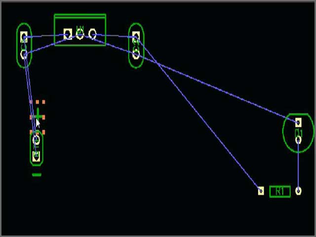

With the new integration available in DipTrace version 4.1.2 and later, engineers can now search and download SnapEDA models, directly from DipTrace’s design environment for instant use in their printed circuit board designs. In fact it revealed an error that I'd made in doing the PCB, so the exercise was worthwhile.Today we are happy to announce our collaboration with DipTrace, a popular schematic capture and PCB design tool that prides itself on its intuitive and easy-to-use interface. Most of the holes were too small, and closed up, but it did allow me to do the rough physical check of the board with respect to case and parts that I needed. Is there anyway to (easily, by multiple selection in tree view) change the dimensions of groups of holes while in FreeCAD?Īnyway, a big thanks, to you members of the forum. So, why did the image disappear, and how do I get it back?Ĥ. No mater how I navigated / scrolled with the mouse, I was unable to see it again.

The last couple of times though, the image of the board totally disappeared when I entered the dimensions to Pad. The first couple of times I went through this I saw the Sketch, then highlighted in green, and then converted to a Pad. I suspect FreeCAD is trying to redraw the whole thing or something each time that value is changed?ģ. Maybe I have a slightly slow computer, but the changing the dimension value in Pad was extremely sluggish. You didn't say, but I assume that I initially open the DXF using the Draft Workbench.Ģ. The main thing I had missed was selecting the button for Create Sketches in DXF Preferences.ġ. I'll go back and look at the first two again, but in the interest of expediency I used the suggestion of sgrogan to crank the "board" out. HolesBeforeExtrusion.JPG (121.51 KiB) Viewed 2409 times HolesAfterExtrusion.JPG (147.32 KiB) Viewed 2409 times DrillBoard.dxf (11.01 KiB) Downloaded 91 times

The purpose of all this is to generate a 0.062" thick STL file that I can print on my (home-built) 3d printer, just to check part fit in an enclosure before I send the board out to fab. So, how do I make the board into a solid, with the holes being holes in it? If I select all, and extrude, what I get is extrusions of these elements, ie lines and circles in the Z direction. I've read other posts, and I'm not even sure if I need to convert to a sketch to do this. ( I did NOT convert it into a sketch, as I'm not really sure how to do this at this point. I'm in the FreeCAD Part workbench, and can import the DXF okay, I've attached a screen shot. I use a printed circuit board program called Diptrace, and have outputted from it a DXF file containing the board outline and holes only. I have a very simple (I think) problem to solve. I'm a bit confused about the usages of all of the different workbenches, and trying to figure it all out.


 0 kommentar(er)
